Overview
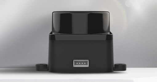
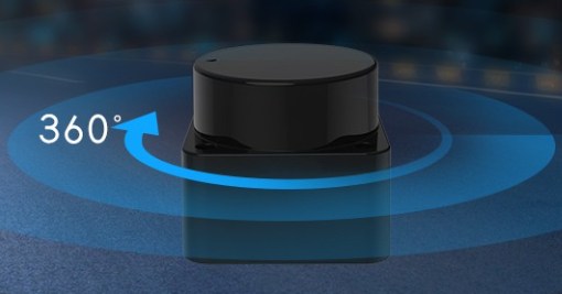
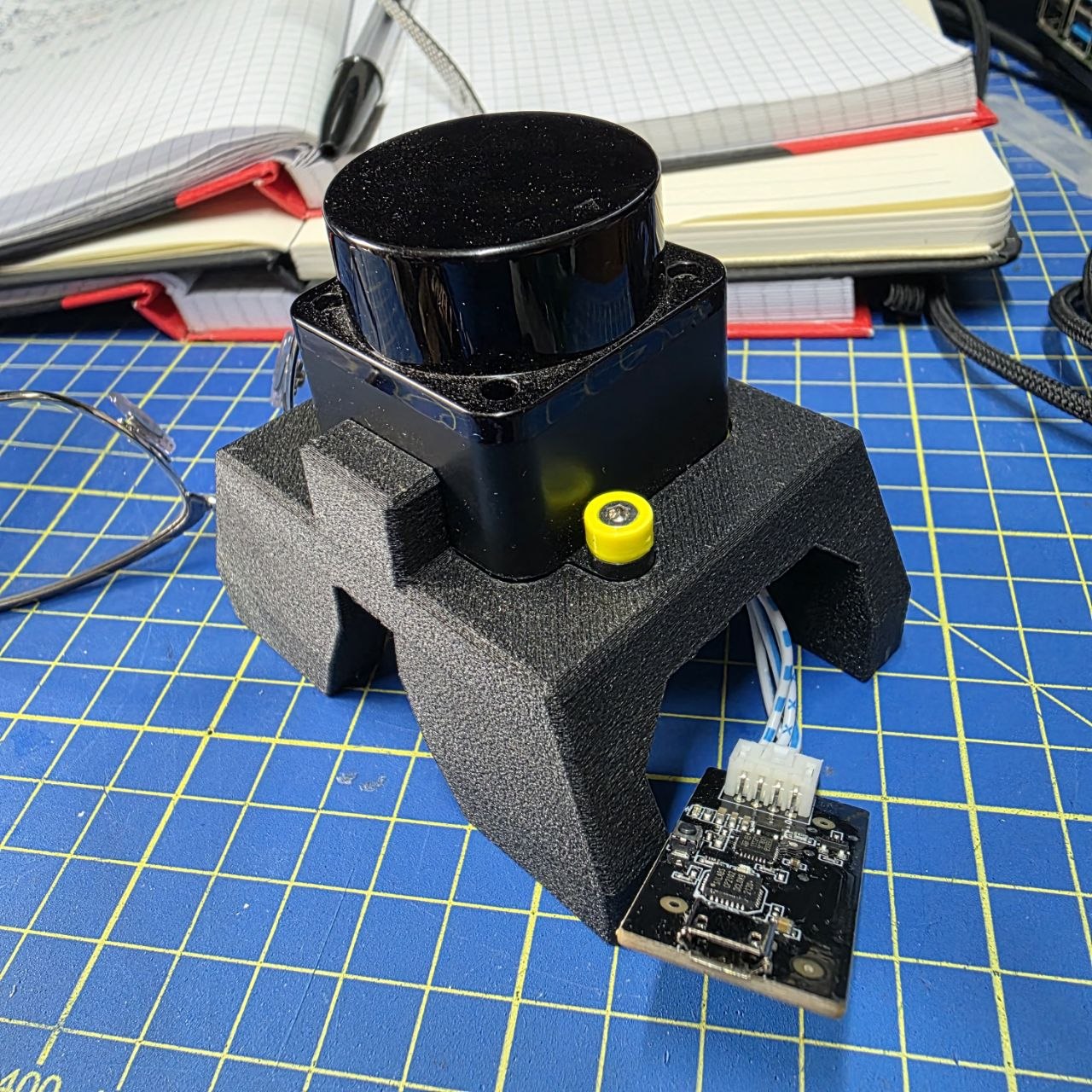
Back in 2021 I backed the LDRobot Kickstarter campaign and got my hands on the LD19 — a compact, affordable DToF 360° lidar I was planning to mount on MyzharBot to improve its obstacle detection. When the sensor arrived, I hit an immediate wall: there was no ROS 2 driver for it. A ROS 1 package existed, but I had already committed to building MyzharBot’s new stack entirely on ROS 2, so that was no help.
Rather than waiting for someone else to write it, I wrote it myself. What started as a quick weekend project to get a /scan topic publishing turned into a proper driver — Lifecycle nodes, Nav2 lifecycle manager integration, full YAML configuration, SLAM Toolbox support, and a URDF 3D model. If the sensor was going to live on my robot, it had to work like a real robot component, not a prototype script.
The repository contains three ROS 2 packages:
-
ldlidar— meta-package that groups the other two, so a singlerosdep installpulls everything in. -
ldlidar_component— the actual driver, implemented as a ROS 2 Lifecycle component. It handles serial communication with the sensor, parses the DToF scan data, and publishessensor_msgs/msg/LaserScan. Being a component means it can be loaded into a shared container process, reducing inter-process overhead. -
ldlidar_node— packages the container executable together with the launch files, YAML parameter files, and the URDF description. This is the entry point most users interact with.
The driver supports the LD19 (tested extensively) and the LD06 (community-reported), and works on ROS 2 Humble and Jazzy.
The sensors can be sourced from:
Installation
Clone the repository into your ROS 2 workspace and install the system dependency:
cd ~/ros2_ws/src/
git clone https://github.com/Myzhar/ldrobot-lidar-ros2.git
sudo apt install libudev-dev
udev rules
The LD19 connects to the host via a CP210x UART/USB adapter that is included in the box. This adapter does more than just bridging serial data: it also supplies power to the sensor and generates the PWM signal that controls the motor rotation speed. Plugging in a single USB cable is all you need to get the lidar spinning and communicating.
NOTE - Direct UART connection: it is possible to wire the LD19 directly to a UART port (e.g. on a Jetson or Raspberry Pi), but in that case you must supply the sensor’s operating voltage and provide the PWM signal yourself to spin the motor — the adapter board handles both automatically.
Without a udev rule, Linux assigns the adapter a generic ttyUSB* name that can change across reboots, and accessing it requires root privileges.
The provided rule matches the adapter by its USB vendor and product IDs (10c4:ea60, the Silicon Labs CP210x) and does two things: it grants read/write access to all users (MODE:="0777") and creates a stable symlink at /dev/ldlidar regardless of which physical USB port you plug into. After installing the rule, comm.serial_port in ldlidar.yaml can be set to /dev/ldlidar and it will always point to the right device.
cd ~/ros2_ws/src/ldrobot-lidar-ros2/scripts/
./create_udev_rules.sh
Build the packages
Build and source:
cd ~/ros2_ws/
rosdep install --from-paths src --ignore-src -r -y
colcon build --symlink-install --cmake-args=-DCMAKE_BUILD_TYPE=Release
echo "source $(pwd)/install/local_setup.bash" >> ~/.bashrc
source ~/.bashrc
Launch Files
The package ships four launch files, each suited to a different use case. Their structure follows the template model I describe in my ROS 2 Python launch file tutorial, and the core bringup uses node composition to load the driver as a component plugin inside a shared container.
Core bringup
Starts a ROS 2 Component Container that loads the LDLidar component as a plugin, plus a robot_state_publisher that publishes the static ldlidar_base → ldlidar_link TF transform and the /robot_description topic.
ros2 launch ldlidar_node ldlidar_bringup.launch.py
Because the node follows the Lifecycle pattern, it starts in the UNCONFIGURED state. Manually trigger the transitions:
ros2 lifecycle set /ldlidar_node configure
ros2 lifecycle set /ldlidar_node activate
With lifecycle manager
Includes the core bringup and adds a Nav2 lifecycle_manager node that handles the configure → activate transitions automatically:
ros2 launch ldlidar_node ldlidar_with_mgr.launch.py
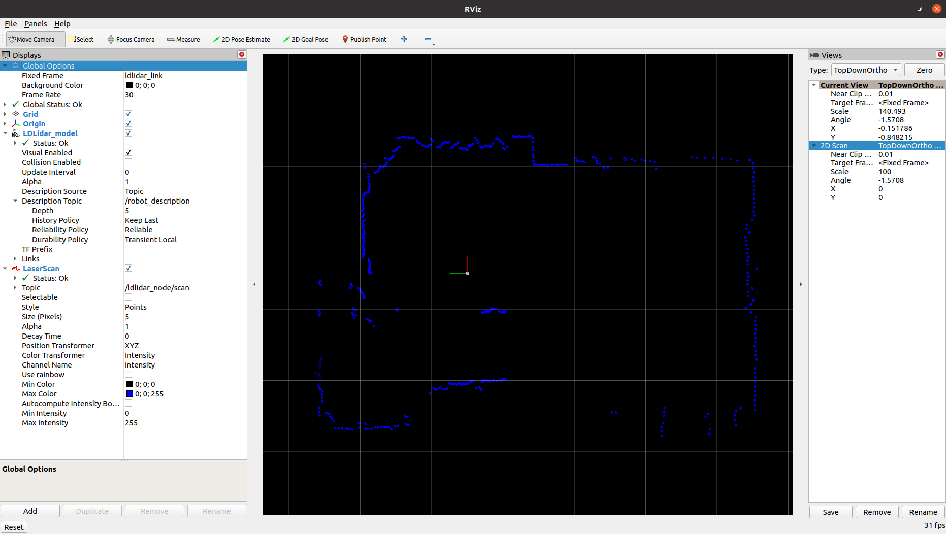
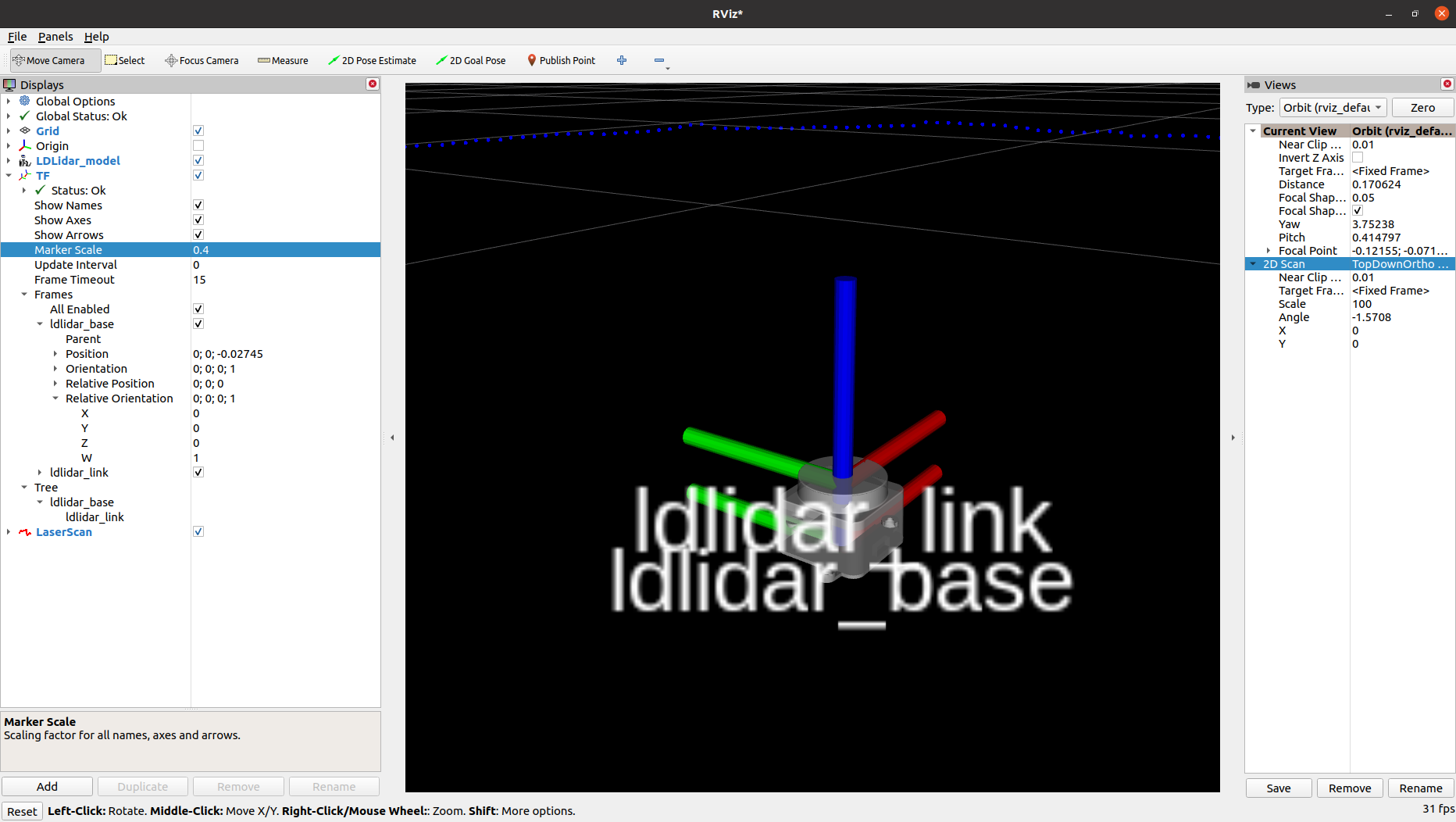
Interactive visualisation in RViz2
Starts the node, the lifecycle manager, and a pre-configured RViz2 instance showing the 2D laser scan. Useful for quick bring-up and sensor validation:
ros2 launch ldlidar_node ldlidar_rviz2.launch.py
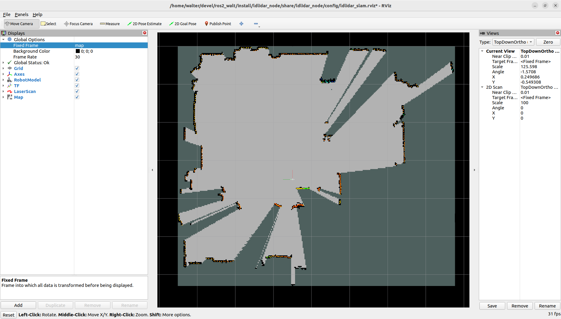
SLAM Toolbox integration
Demonstrates how to use the driver together with SLAM Toolbox to build a 2D occupancy map for navigation:
ros2 launch ldlidar_node ldlidar_slam.launch.py

ldlidar_slam.launch.pyas a learning reference: beyond its practical use, this launch file is a concrete, working example of how to combine lifecycle nodes and node composition in a single Python launch file — a pattern that recurs in any production-grade ROS 2 bringup. It shows how to spin up a composable container, load a lifecycle component into it, and wire alifecycle_managerto drive the configure → activate sequence automatically.
Node Parameters
All parameters are loaded from ldlidar.yaml and can be edited before launching.
| Parameter | Description |
|---|---|
general.debug_mode |
Enable verbose debug logging |
comm.serial_port |
Serial port path (e.g. /dev/ldlidar) |
comm.baudrate |
Serial port baud rate |
comm.timeout_msec |
Serial communication timeout in ms |
lidar.model |
Sensor model: LDLiDAR_LD06, LDLiDAR_LD19, LDLiDAR_STL27L
|
lidar.rot_verse |
Rotation direction: CW (upside-down mount) or CCW
|
lidar.units |
Distance units: M, CM, or MM
|
lidar.frame_id |
TF frame name for the lidar link |
lidar.bins |
Scan size: 0 = dynamic (matches rotation speed), fixed value for SLAM Toolbox compatibility |
lidar.range_min |
Minimum valid scan distance |
lidar.range_max |
Maximum valid scan distance |
lidar.enable_angle_crop |
Enable angular field-of-view cropping |
lidar.angle_crop_min |
Start angle of the cropped region (degrees) |
lidar.angle_crop_max |
End angle of the cropped region (degrees) |
lidar.binsto a fixed value (e.g.455) to keep a constant number of scan points per revolution, which is required for SLAM Toolbox compatibility.
3D Model for URDF
Integrating the sensor into a robot’s URDF requires a 3D model for visualization and collision geometry — and LDRobot didn’t provide one. So I modelled the LD19 myself in OnShape, matching the real sensor dimensions as accurately as I could.
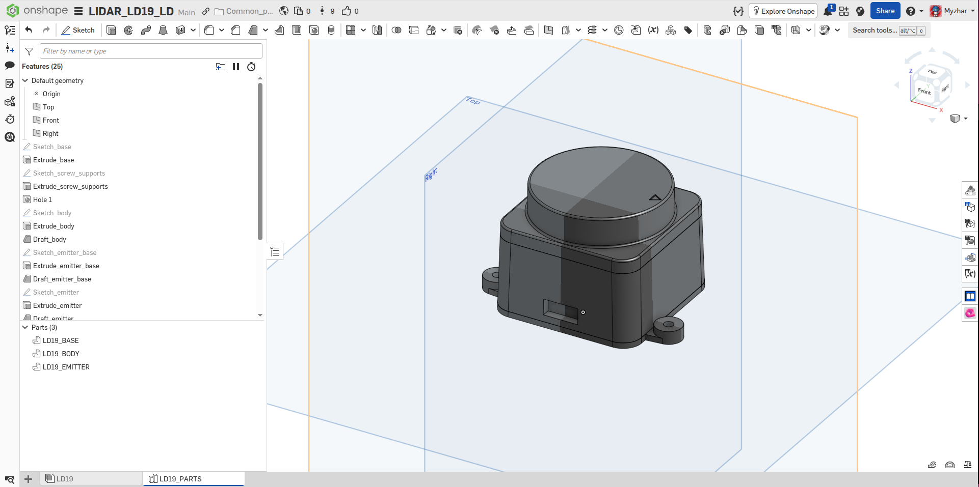
The STEP and STL files exported from the model are also included in the 3d_model/ folder of the repository, ready to drop into your own URDF or Xacro description.
Nav2 Integration
The driver is built around the Nav2 Lifecycle node architecture, which means it integrates cleanly into any Nav2-based navigation stack.
The key integration points are:
-
TF transform: the
ldlidar_bringup.launch.pylaunch file starts arobot_state_publisherthat publishes theldlidar_base → ldlidar_linktransform. Your robot’s URDF must provide thebase_link → ldlidar_basetransform to complete the chain. -
Lifecycle management: include
ldlidar_with_mgr.launch.pyin your robot’s bringup launch file. The embedded Nav2lifecycle_managerwill automatically handle configure/activate transitions, exactly like any other Nav2-managed node. -
YAML configuration: update
ldlidar.yamlto match your robot’s serial port, model, and mounting orientation before launching. -
Scan topic: the activated node publishes
sensor_msgs/msg/LaserScanon/ldlidar_node/scan, which is consumed directly by Nav2’s costmap and AMCL nodes.
Videos
LD19 lifecycle node bring-up and live scan visualisation in RViz2.
LD19 tested outdoors — demonstrating range and stability in open environments.
Benchmarking
Performance can be measured with the NVIDIA Isaac ROS ros2_benchmark package:
cd ~/ros2_ws/src/ldrobot-lidar-ros2/ldlidar_node/test/
launch_test ldlidar_benchmark.py
Typical results on a mid-range x86_64 laptop show a mean frame rate of ~10 fps (matching the sensor’s native rotation speed) with an end-to-end latency well under 1 ms and zero missed frames:
+--------------------------------------------------------------------------------------------+
|                                  LD Lidar Live Benchmark                                   |
|                                        Final Report                                        |
+--------------------------------------------------------------------------------------------+
| [Scan] Delta between First & Last Received Frames (ms) : 4900.138                          |
| [Scan] Mean Playback Frame Rate (fps) : 9.936                                              |
| [Scan] Mean Frame Rate (fps) : 9.936                                                       |
| [Scan] # of Missed Frames : 0.000                                                          |
| [Scan] # of Frames Sent : 49.000                                                           |
| [Scan] First Sent to First Received Latency (ms) : 0.075                                   |
| [Scan] Last Sent to Last Received Latency (ms) : 0.113                                     |
| [Scan] First Frame End-to-end Latency (ms) : 0.075                                         |
| [Scan] Last Frame End-to-end Latency (ms) : 0.113                                          |
| [Scan] Max. End-to-End Latency (ms) : 0.172                                                |
| [Scan] Min. End-to-End Latency (ms) : 0.049                                                |
| [Scan] Mean End-to-End Latency (ms) : 0.098                                                |
| [Scan] Max. Frame-to-Frame Jitter (ms) : 100.142                                           |
| [Scan] Min. Frame-to-Frame Jitter (ms) : 0.000                                             |
| [Scan] Mean Frame-to-Frame Jitter (ms) : 17.865                                            |
| [Scan] Frame-to-Frame Jitter Std. Deviation (ms) : 12.793                                  |
+--------------------------------------------------------------------------------------------+
| Baseline Overall CPU Utilization (%) : 0.000                                               |
| Max. Overall CPU Utilization (%) : 79.167                                                  |
| Min. Overall CPU Utilization (%) : 0.000                                                   |
| Mean Overall CPU Utilization (%) : 1.179                                                   |
| Std Dev Overall CPU Utilization (%) : 3.964                                                |
+--------------------------------------------------------------------------------------------+
| [metadata] Test Name : LD Lidar Live Benchmark                                             |
| [metadata] Test File Path : /home/walter/devel/ros2/ros2_walt/src/ldrobot-lidar-ros2/ldlidar_node/test/ldlidar_benchmark.py |
| [metadata] Test Datetime : 2024-11-25T22:12:54Z                                            |
| [metadata] Device Hostname : walter-Legion-5-15ACH6H                                       |
| [metadata] Device Architecture : x86_64                                                    |
| [metadata] Device OS : Linux 6.8.0-40-generic #40~22.04.3-Ubuntu SMP PREEMPT_DYNAMIC Tue Jul 30 17:30:19 UTC 2 |
| [metadata] Idle System CPU Util. (%) : 0.333                                               |
| [metadata] Benchmark Mode : 3                                                              |
+--------------------------------------------------------------------------------------------+
What started as a weekend hack to get a Kickstarter lidar talking to ROS 2 ended up as a full-featured driver that I’ve been running on MyzharBot ever since. If it saves you the same headache it saved me, that’s exactly why I published it.
Happy robotics programming! 🤖